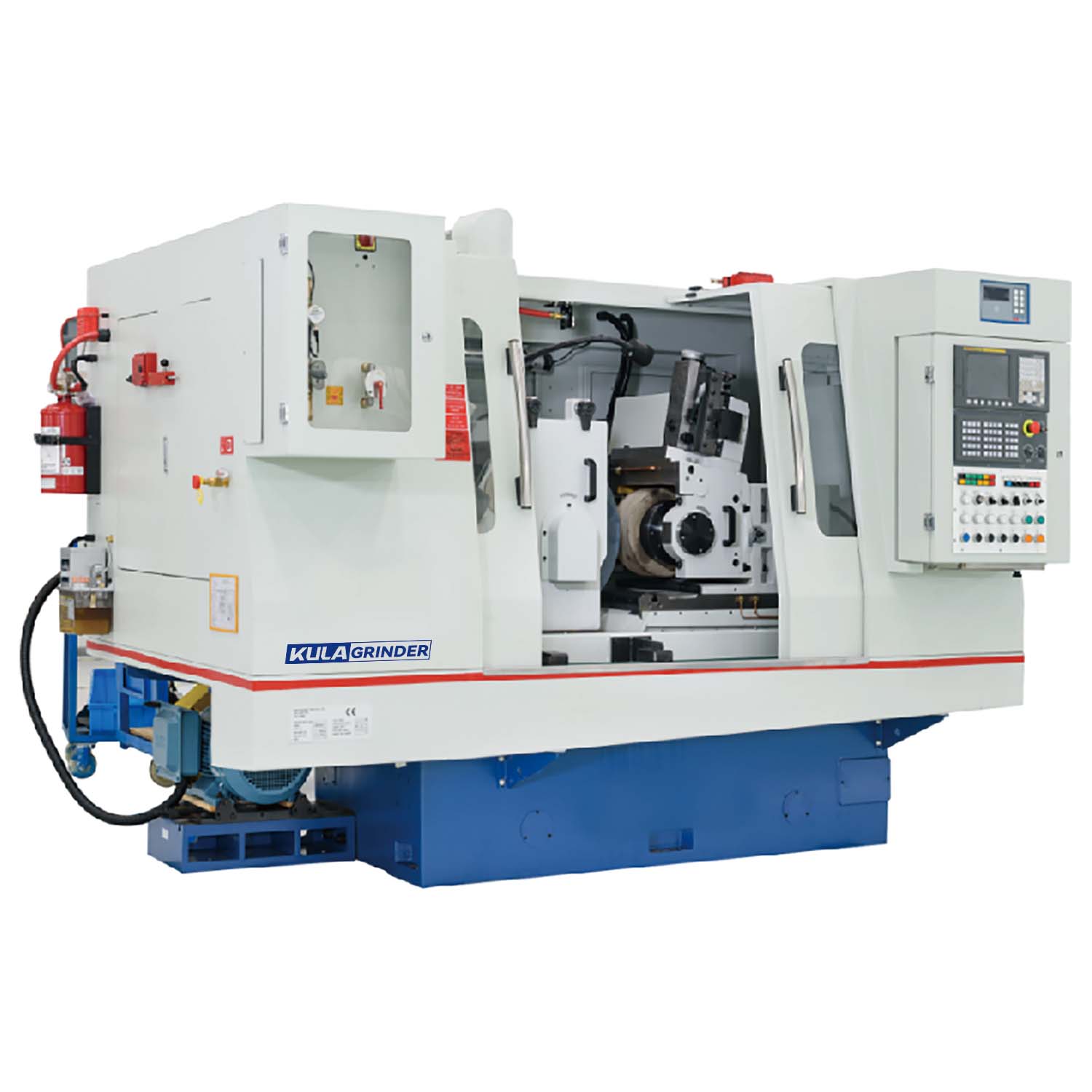
Achieving consistent sub-micron diameter control in centerless grinding often feels like an impossible dark art. Operators frequently treat the entire process like magic rather than science. In reality, it relies on a strict combination of thermodynamic management, mechanical rigidity, and precise CNC setups. For manufacturers facing high scrap rates or unstable Cpk in high-volume production, upgrading or optimizing your equipment represents a critical capital decision. Poor stability severely impacts daily yield and overall part quality. You cannot rely solely on operator intuition to hit exact tolerances day after day. This comprehensive guide breaks down the complex physics behind diameter stability. We will explore core setup parameters deeply. We will also detail the hardware features you must evaluate when investing in a high-precision grinding solution. By mastering these variables, you transform unpredictable scrap into a highly controlled, profitable manufacturing process.
Key Takeaways
Stable diameter control requires perfectly synchronized regulating wheel angles, workblade heights, and continuous thermal management.
Through feed grinding demands specific machine rigidity compared to infeed processes to prevent taper and chatter over long production runs.
Evaluating a new CNC centerless grinder should focus heavily on hydrostatic spindles, bed casting material (e.g., epoxy granite), and automated dressing compensation.
Successful implementation relies as much on operator training and environmental control as it does on the machine's stated tolerances.
The Business Case for Stability in Precision Centerless Grinding
Unstable diameter control leads to compounding downstream costs rapidly. Excessive scrap wastes expensive raw materials. Scrap also destroys the machine time already invested in your parts. Frequent manual interventions slow down cycle times significantly. They create massive bottlenecks in your quality control departments. We must aggressively move beyond "good enough" tolerances.
True success relies on defining your process capability index (Cpk) rigorously. You need continuous roundness and straightness across thousands of parts. A highly capable process minimizes the need for constant, operator-driven micro-adjustments. A Cpk of 1.33 or higher means your process variation stays well within acceptable tolerance limits. Achieving this metric requires absolute mechanical stability.
Consider the hidden cost of dimensional drift. Thermal expansion and wheel wear secretly erode profit margins during tight-tolerance runs. As temperatures fluctuate throughout a production shift, the machine frame naturally shifts. This microscopic movement fundamentally alters the grinding zone. If you ignore these minute changes, you will inevitably produce non-conforming parts. Implementing robust stability measures protects your bottom line. It ensures every single component leaves the machine ready for final assembly.
Core Setup Parameters for a CNC Centerless Grinder
A perfectly configured CNC centerless grinder transforms raw metal into flawless cylinders. Workblade height and geometry form the absolute foundation of your setup. You must calculate the optimal height above centerline carefully. Operators typically set this height between 1/2 to 1/4 of the part diameter. Proper height ensures rapid rounding without inducing destructive chatter.
You must also select the correct blade material. Carbide works exceptionally well for most standard steels. PCD (polycrystalline diamond) handles highly abrasive alloys and aerospace materials better. A damaged workblade ruins your geometry instantly.
Next, consider your regulating wheel dynamics. You must set the exact inclination angle. This precise angle controls both the feed rate and the part rotation speed. CNC controls easily manage truing and dressing operations today. You utilize these controls to generate a precise hyperbolic shape on the wheel. This shape guarantees the required line contact along the entire length of the workpiece.
Coolant application directly impacts your thermal stability. Position high-pressure nozzles precisely to break the persistent air barrier surrounding the rapidly spinning grinding wheel. Proper coolant filtration prevents microscopic swarf recirculation. Temperature regulation systems keep the fluid consistent. These proactive steps maintain dimensional stability over an entire eight-hour shift.
Set workblade height accurately to eliminate chatter vibrations.
Dress regulating wheels to a true hyperbolic profile.
Deliver high-pressure coolant directly into the grinding zone.
Filter coolant diligently to prevent surface scratches.
Optimizing Through Feed Grinding for Shaft Centerless Grinding
Let us compare through feed and infeed mechanics briefly. Infeed grinding plunges the wheel into a stationary rotating part. Continuous through feed grinding constantly pushes the part axially past the wheels. This continuous motion presents unique engineering challenges. Maintaining a consistent diameter across long parts requires absolute precision.
When executing shaft centerless grinding, guide plate alignment becomes absolutely crucial. You must establish perfect entry and exit guide alignment. If alignment fails even slightly, you risk tapering or barrel-shaping the workpiece. Long shafts easily suffer from "snake" grinding defects if left unsupported. To prevent this, secure the guides firmly and indicate them precisely parallel to the regulating wheel face.
Managing your stock removal rates remains equally critical. You must balance aggressive roughing passes against delicate finishing passes. Aggressive roughing removes material quickly but generates immense heat. This heat causes thermal distortion or work hardening in complex alloys like Inconel. Spread the total removal across multiple lighter passes. This proven strategy ensures a stress-free, accurate finish.
Follow these specific steps for optimal setup:
Align entry guides exactly parallel to the regulating wheel face.
Set exit guides slightly lower than your entry point.
Distribute stock removal evenly across multiple machine passes.
Monitor part temperature immediately after the exit chute.
Upgrading your shop floor requires careful hardware evaluation. Base and casting rigidity determine your ultimate success in precision centerless grinding. Cast iron offers excellent damping properties for standard applications. Mineral cast or epoxy granite beds provide even superior vibration absorption. These heavy bases are completely non-negotiable. They absorb high-frequency vibrations generated during aggressive, continuous grinding cycles.
Spindle design separates average machines from truly exceptional ones. Evaluate hydrostatic or hydrodynamic spindle bearings carefully. They ensure zero metal-to-metal contact during operation. This specialized fluid film provides incredible longevity. It also delivers superior surface finish capabilities compared to traditional rolling element bearings.
Modern controls feature highly advanced CNC capabilities. Sub-micron glass scale feedback allows for immediate, automatic wheel wear compensation. Acoustic emission monitoring automates touch-dressing processes flawlessly. The sensor detects the exact microsecond the diamond touches the wheel, preventing unnecessary wheel loss.
Automation readiness completes your evaluation package. You should integrate gantry loaders and vibratory bowls early. In-process gauging systems feed dimensional data directly back to the control. These elements enable true lights-out manufacturing and massive productivity gains.
Spindle Bearing Technology Comparison
Spindle Type
Friction Level
Vibration Damping
Best Application
Rolling Element
Moderate
Average
Standard tolerance production
Hydrodynamic
Very Low
Excellent
High-speed, continuous grinding
Hydrostatic
Zero (at low speeds)
Superior
Sub-micron precision requirements
Implementation Risks and Operator Adoption
The current skills gap reality threatens many new machine installations. Modern CNC greatly simplifies complex dressing and compensation routines. However, your operators still need a fundamental understanding of centerless physics. They must know exactly how the part interacts with the workblade. Without this foundational knowledge, they cannot troubleshoot unpredictable chatter or taper effectively.
Environmental variables easily sabotage your best engineering efforts. Machine capabilities are entirely voided by poor ambient temperature control. A factory floor fluctuating by ten degrees will ruin your sub-micron tolerances instantly. You must invest in robust climate management. This includes dedicated coolant chillers and ambient HVAC systems.
Finally, carefully assess vendor support and turnkey solutions. Simply buying a machine is insufficient. Evaluate vendors based on their dedicated application engineering expertise. Demand comprehensive runoff testing to prove out the process entirely before shipping. Local service availability ensures your production line never stops for long. A strong vendor acts as a true manufacturing partner.
Shortlisting Your Next Grinding Solution
Defining your Request for Quote (RFQ) requires exceptional clarity and detail. You must specify exact tolerances, material hardness variations, and specific cycle time requirements. Approach OEMs with detailed part prints and historical capability data. Clear communication upfront prevents mismatched machine capabilities later.
Next steps involve rigorous, documented validation. We strongly recommend demanding a detailed time-study from the machine builder. Require a capability runoff using your actual production materials. Complete this step long before issuing any final purchase order.
Real-world testing exposes hidden process flaws immediately. It guarantees the proposed solution meets your stringent, high-volume production standards. Thorough validation protects your capital investment.
Conclusion
Achieving reliable, repeatable roundness and straightness is a strict science. It relies heavily on rigidity, geometry, and thermal control, never on luck. Investing in a capable machine shifts the heavy burden of accuracy away from manual operator intuition. It places that burden firmly onto repeatable machine kinematics.
Invest in robust machine kinematics rather than depending on operator intuition.
Audit your current scrap rates to identify areas where dimensional drift erodes your profits.
Review your existing workblade and regulating wheel setups against industry benchmarks.
Contact experienced application engineers for a comprehensive process evaluation before finalizing capital expenditures.
FAQ
Q: What causes chatter in a CNC centerless grinder setup?
A: Chatter typically results from incorrect workblade height. If set improperly, the part bounces between the wheels. Poor machine rigidity also causes high-frequency vibrations. Finally, using a grinding wheel deemed too hard for your specific application prevents proper breakdown. We recommend lowering your workblade slightly or selecting a softer wheel grade to eliminate these surface finish defects quickly.
Q: How does through feed grinding differ from infeed grinding in diameter control?
A: Through feed constantly moves your part axially past the wheels. This method works perfectly for straight cylinders and long shafts. It requires absolute guide plate alignment to prevent tapering. Infeed grinding plunges the wheel directly into a stationary, rotating part. We use infeed setups primarily for multi-diameter components or flanged parts where axial movement remains impossible.
Q: Can a modern CNC centerless grinder run unattended?
A: Yes, they run unattended beautifully. However, successful lights-out operation requires proper hardware integration. You must install automatic in-process gauging to monitor dimensional drift. Automated wheel dressing systems relying on acoustic sensors keep the wheel sharp. Finally, you need reliable robotic or gantry feeding systems to load parts and manage natural wear safely without manual intervention.
Q: How often should the regulating wheel be dressed?
A: Dressing frequency depends entirely on your specific material and tolerance requirements. High-end CNC setups monitor part drift continuously via post-process gauging. They trigger a dressing cycle automatically only when statistical variations make it absolutely necessary. This data-driven approach maximizes wheel life while guaranteeing sub-micron precision across your entire production run.