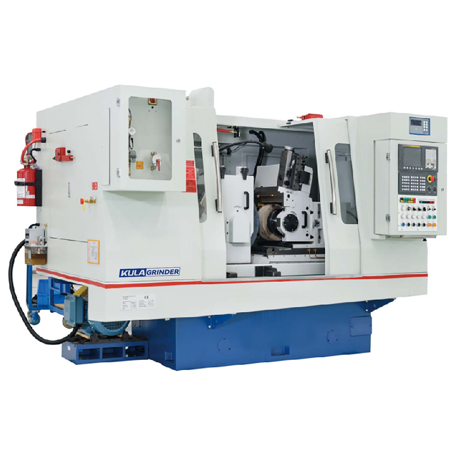
Manufacturing precision often hinges on selecting the exact right equipment for specific component designs. You must match specific workpiece geometries to the correct machining process. Doing so minimizes cycle times and avoids costly material scrap. A centerless grinding machine offers unmatched throughput for many production environments. However, it operates on a fundamentally different principle than conventional lathes or mills. It relies heavily on a regulating wheel and a work rest blade instead of traditional spindle centers.
This unique three-point setup creates strict geometric prerequisites. Not every shape fits this operational profile. Engineers and production managers often struggle to determine if their parts meet these rigid structural requirements. We wrote this article to clarify those physical boundaries. You will discover how different part profiles behave inside the machining zone. We provide a technical evaluation framework specifically designed for your part portfolio. This guide helps you determine definitively if your components are structurally viable for these highly efficient operations.
Key Takeaways
Ideal Profiles: Uninterrupted cylinders, tapered shafts, and multi-diameter pins are highly suitable.
Process Alignment: The chosen centerless grinding process (thru-feed, in-feed, or end-feed) dictates the exact shapes the machine can accept.
Volume Dependency: Centerless grinding is optimized for high volume grinding; complex shapes requiring in-feed setups demand larger batch sizes to offset longer tooling changeovers.
Limiting Factors: Parts with severe asymmetry, deep axial keyways, or non-circular cross-sections generally require alternative grinding methods.
The Mechanics of Shape Compatibility in a Centerless Grinding Machine
To understand which shapes succeed, you must first understand the physics of the operation. The system does not hold the part rigidly in a chuck. Instead, it relies on a dynamic balance of forces.
The Three-Point Constraint System
We rely on three distinct mechanical components to support and drive the workpiece. First, the main grinding wheel spins at high speeds to remove material. Second, the regulating wheel (usually a rubber-bond abrasive) spins at a much slower speed to control the rotation of the part. Third, the work rest blade holds the component at the correct vertical height between the two wheels. This creates a floating constraint system. The part finds its own center based on its outside diameter.
Why Centers Matter (or Don't)
Removing the need for center holes provides a massive advantage for specific geometries. Fragile, extremely long, or thin-walled parts often bow under the axial pressure applied by traditional tailstocks. We eliminate this compressive pressure entirely. The workpiece receives continuous line support along its entire length from the work rest blade. This continuous support prevents deflection. It allows manufacturers to hold micro-inch tolerances on delicate tubing or slender guide wires.
Risk Factor: The Lobing Phenomenon
Because the part floats, its starting geometry heavily influences the final roundness. Poor initial shapes can cause out-of-roundness. We call this phenomenon "lobing." A part might measure the exact same diameter across any two points but still form a Reuleaux triangle shape rather than a perfect circle. You must control the blade angle and centerline height to correct this geometry. Adjusting the blade forces the high spots of the part to contact the grinding wheel more aggressively, eventually forcing the part into perfect cylindricity.
Viable Workpiece Geometries and Required Setup Types
We categorize workpiece shapes by the specific feeding method required to process them. Each geometry demands a distinct machine setup.
Straight Cylindrical Parts (Thru-Feed Grinding)
Straight cylinders represent the absolute ideal shape for this technology. The regulating wheel tilts at a slight angle (usually one to five degrees). This tilt creates an axial force. The part drives itself forward smoothly through the machining zone.
Examples: Dowel pins, linear bearing shafts, piston rings, and cylindrical rollers.
Evaluation Criteria: The component must have a constant outside diameter. You cannot have interfering shoulders, flanges, or heads protruding from the main body.
Production Reality: This method offers the highest possible throughput. Parts feed end-to-end continuously. They enter the front chute and exit the rear chute without any machine stoppage.
Best Practice: Always ensure incoming blanks have consistent straightness. Bent shafts will bind between the wheels. This binding causes irregular feed rates, thermal damage, and potential wheel breakage.
Stepped, Profiled, and Multi-Diameter Parts (In-Feed Grinding)
When a part features multiple diameters or obstructing shoulders, it cannot pass all the way through the machine. You must use a plunge-style operation.
Evaluation Criteria: You must introduce the workpiece from the top or side using an automated loader or manual operator. The grinding wheel needs a precise dress. It must match the exact inverse profile of your target component.
Production Reality: This centerless grinding process inherently involves slower cycle times than continuous thru-feeding. You also face increased tooling complexity. Wheel dressing requires high precision, utilizing rotary diamond truing tools to maintain the complex wheel shape over thousands of cycles.
Tapered and Headed Parts (End-Feed Grinding)
This hybrid approach blends principles from both thru-feed and in-feed setups. It handles parts that require a tapered finish but have a physical limit on how far they can travel.
Examples: Tapered roller bearings and specific aerospace fluid-control fasteners.
Evaluation Criteria: The part feeds into the gap laterally until it hits a physical end stop. This barrier stops the axial movement. The wheels then grind the required taper before a mechanism ejects the part back out the front.
Production Reality: This remains a highly specialized setup. You need rigorous machine calibration. Maintaining accurate taper angles over long production runs takes immense skill. Thermal expansion in the machine casting can easily shift the taper angle if left unchecked.
Incompatible or High-Risk Geometries
Some shapes simply violate the fundamental physics of the three-point constraint system.
Examples: Components featuring large flats, deep axial keyways, heavy eccentric weight distribution, or square/hexagonal profiles.
Why They Fail: The process relies on continuous rotational contact. Interruptions in the diameter create a physical void. The part loses crucial traction against the regulating wheel. This sudden loss of control drops the part slightly on the blade. The grinding wheel then takes a massive, uncontrolled bite of material. This leads to severe chatter, loss of dimensional tolerance, or catastrophic machine crashes.
Common Mistake: Attempting to process parts with deep keyways by simply slowing down the regulating wheel. The interrupted cut will inevitably cause part deflection, regardless of rotational speed. These geometries strictly require alternative methods.
Centerless vs. Traditional Cylindrical Part Grinding: A Decision Framework
Manufacturing engineers frequently face a critical business problem. You must route a newly designed part to the correct department. Deciding whether to send a batch to a between-centers grinder or a centerless platform dictates your profit margins. We evaluate these routing decisions across several key engineering dimensions.
Tolerance & Concentricity
According to ASME Y14.5 Geometric Dimensioning and Tolerancing standards, concentricity and roundness mean different things. Traditional cylindrical part grinding excels at concentricity. It holds the workpiece on specific central axes (center holes). This guarantees the outer diameter remains perfectly concentric to those center points. Centerless equipment operates differently. It references the outer diameter itself. It produces exceptional overall O.D. roundness, but it cannot correct a pre-existing concentricity error from a previous lathe operation.
Handling Thin-Walled or Fragile Parts
The centerless approach wins easily here. As discussed, it provides continuous line support. Traditional centers apply axial clamping pressure. This pressure bows fragile materials. If you grind thin titanium tubes on a between-centers machine, the tube will deflect away from the wheel in the middle, creating an hourglass shape.
Setup Time vs. Run Time
Between-centers equipment allows for faster changeovers. You simply adjust the tailstock, load the new program, and run. This makes it ideal for low-volume, high-mix production schedules. Conversely, centerless equipment requires much longer setup times. You must change the work rest blade, adjust the regulating wheel housing, true the wheels, and dial in the centerline height. However, once running, it delivers drastically shorter cycle times.
Comparison of Machine Capabilities
Evaluation Metric
Between-Centers Machining
Centerless Machining
Primary Geometric Reference
Center holes (True Axis)
Outside Diameter (O.D.)
Concentricity Control
Excellent
Moderate (Depends on incoming blank)
Roundness Capability
Very Good
Exceptional
Part Support Mechanism
Axial endpoints only
Continuous full-length line support
Changeover Speed
Fast (Ideal for small batches)
Slow (Requires tooling adjustments)
Cycle Time Efficiency
Moderate
Extremely Fast
Scalability: When Geometry Meets High Volume Grinding
Understanding shape compatibility only solves half the equation. You must also evaluate how that shape scales in a production environment. Complex geometries often require significant upfront investment to process accurately.
ROI Thresholds
You must calculate if a specific shape justifies the initial setup cost. Complex stepped profiles require custom-dressed wheels. A 500-piece batch cannot absorb a four-hour tooling changeover. The complex dressing process destroys profitability for short runs. Conversely, massive production runs easily absorb this upfront time investment. The rapid cycle time eventually overtakes the initial setup penalty. You must identify the breakeven point based on your hourly shop rate.
Tooling Costs
Assess the physical price of custom tooling. You need specific work rest blades milled to match stepped parts. You also wear out diamond truing tools much faster when dressing aggressive inverse profiles into the wheels. Symmetrical, straight cylinders avoid these costs entirely. They use standard flat blades and simple straight wheel dresses.
Automation Compatibility
Evaluate how easily you can feed the desired shape automatically. True high volume grinding relies entirely on seamless automation. Vibratory bowls handle small, symmetrical dowel pins effortlessly. Step feeders organize longer linear shafts, dropping them one by one into the thru-feed chute. However, asymmetrical parts with heavy heads require expensive robotic gantry loaders. The robot must pick up the component, orient it perfectly, and lower it onto the blade for an in-feed cycle.
Quality Control Integration
Maintaining zero-defect compliance requires constant monitoring. High-speed lines integrate in-process gauging systems directly into the exit path. Laser micrometers scan the geometry of every single exiting part. If the diameter grows by two microns due to wheel wear, the gauge sends a signal back to the machine. The CNC controller automatically advances the wheel head to compensate. Straight cylinders accommodate these laser gauges easily. Multi-diameter profiled parts require much more complex probing systems to measure multiple steps simultaneously.
Conclusion
Workpiece geometry dictates grinding methodology. Your part's shape, weight distribution, and feature continuity directly determine whether centerless machining will succeed. Straight cylinders and gently tapered pins thrive in this environment, offering incredible throughput. Highly asymmetrical parts with deep keyways or flats pose significant risks and require alternative routing.
We strongly emphasize evaluating part drawings against these physical capabilities early in the Design for Manufacturing (DFM) stage. Identifying a problematic keyway early prevents massive downstream production bottlenecks. If engineers modify the design slightly, they can often unlock much cheaper, faster manufacturing methods.
As a next-step action, we recommend conducting a feasibility study. Send a representative batch of your target components to a machine manufacturer. Request a formal test grind. This empirical data will validate your geometric assumptions and prove the cycle time capabilities before you commit to full-scale production tooling.
FAQ
Q: Can a centerless grinding machine process parts with blind holes?
A: Yes, as long as the outer diameter remains uninterrupted and balanced, the internal blind hole does not affect the external centerless grinding process. The machine references the outside surface only.
Q: What is the maximum and minimum length-to-diameter (L/D) ratio for centerless grinding?
A: Physical limits depend entirely on the machine size. Highly short parts (low L/D ratio) may tumble between the wheels instead of rotating smoothly. Extremely long parts (high L/D ratio) require outboard support attachments to prevent sagging. Generally, L/D ratios between 1:1 and 20:1 run comfortably without heavy custom fixtures.
Q: Can materials like plastics or ceramics be ground on a centerless machine?
A: Yes. The underlying geometric shape principles remain exactly the same. However, you must adapt the tooling. Hard ceramics require specialized diamond abrasive wheels. Softer plastics need customized coolant strategies to prevent melting and wheel loading. Feeding mechanisms might also need adjustment for lighter materials.
Q: How do you grind a part that has a heavy head on one end?
A: You must use an in-feed grinding setup. The heavy head remains outside the machining zone or sits in a designated relief area. We utilize specialized work rest blades designed for stepped profiles. You may also need counter-balancing techniques or overhead hold-down rollers to prevent the heavy end from tipping the part upward.