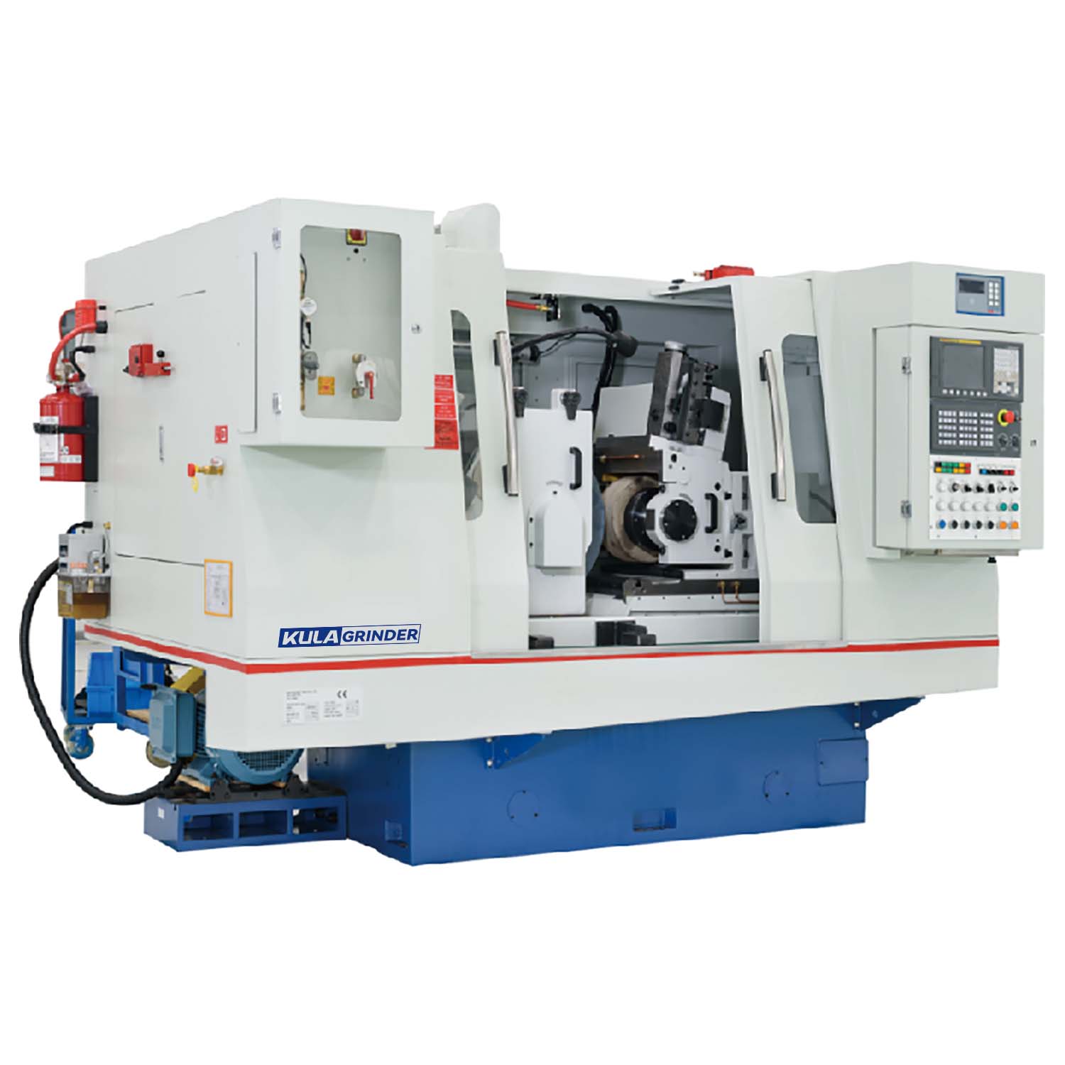
Traditional machining often struggles against a stubborn production bottleneck. Mounting parts between centers or inside chucks steals valuable setup time. It severely restricts your continuous throughput capabilities. You lose minutes on every single batch just securing the workpiece. Enter the centerless grinding machine. This equipment completely removes static fixtures from the equation. Instead, it relies on dynamic physical forces to secure the material. The wheels and a support blade trap the component precisely in place. Removing the need for spindle mounting changes everything for modern machine shops. Manufacturers unlock truly scalable, continuous production for round components. You will learn the exact physics making this possible. We will explore various feed mechanisms suited for different geometries. We also compare it directly against traditional turning and grinding methods. Finally, we highlight why this dynamic setup excels in modern, automated manufacturing environments.
Key Takeaways
The workpiece is held in a dynamic pocket created by three components: the grinding wheel, the regulating wheel, and the workblade.
Because the part is supported along its entire length, deflection is virtually eliminated, allowing for tighter tolerances on brittle or long, thin parts.
The absence of static fixturing enables continuous, automated feeding, making it the definitive choice for high volume grinding.
Setup complexity is higher than traditional methods; the process requires precise mathematical alignment, making it less viable for low-volume, high-mix production runs.
The Physics of the Centerless Grinding Process
Understanding the centerless grinding process requires shifting your perspective. You must forget clamps, jaws, and tailstocks. Instead, imagine a dynamic trap where opposing physical forces hold the component in perfect equilibrium. We call this the three-point dynamic pocket. It relies entirely on the precise interaction of three core components.
The Three-Point Dynamic Pocket
This pocket replaces traditional workholding entirely. Each component plays a specific role in keeping the part stable.
The Grinding Wheel: This is the aggressive component. It spins at exceptionally high speeds. It performs the actual material removal. Crucially, its rotation pushes the workpiece downward against the support structure and laterally into the opposing wheel.
The Regulating (Feed) Wheel: This wheel typically utilizes a rubber-bonded abrasive. It spins much slower than the grinding wheel. It acts as a frictional brake. It dictates the exact rotational speed of your part. Furthermore, tilting this wheel creates the axial force pulling the part through the machine.
The Workblade (Rest Blade): This stationary component supports the workpiece from beneath. The blade features an angled top edge. This specific angle wedges the component constantly against the two wheels. It prevents the part from dropping or flying out of the grinding zone.
Center Height Geometry
You cannot simply place the workpiece exactly on the centerline between the two wheels. Doing so creates a critical geometric error. Any low spot on the part will shift into the wheel, generating a high spot exactly 180 degrees opposite it. The result is a Reuleaux triangle. The part will have a constant diameter, but it will not be round.
To solve this, machinists elevate the workblade. They place the component's center slightly above the centerlines of the two wheels. This elevation breaks the 180-degree symmetry. When a low spot contacts one wheel, the resulting high spot generates at an irregular angle. Continuous rotation gradually blends these points away. This mathematical shift guarantees a perfectly round final cylinder.
Compressive vs. Bending Force
Traditional lathes and grinders hold parts at the ends. When the cutting tool engages the middle of the shaft, it applies lateral pressure. This creates bending force. Long, thin parts easily bow or deflect under this pressure. Centerless technology operates differently. The grinding wheel pushes the part directly into the regulating wheel and the blade. The component experiences pure compressive force. The blade supports its entire length simultaneously. This eliminates mid-part deflection entirely.
Common Mistake: Setting the workblade angle too steep. This causes the grinding wheel to pinch the part aggressively. It often results in severe chatter marks on your finished surface. Always match the blade angle to the specific material and diameter.
Solution Categories: Thru-Feed vs. In-Feed Mechanisms
Engineers adapt the core physics to handle different part geometries. The way a component moves through the dynamic pocket dictates the machine's setup. We categorize these setups into three primary feed mechanisms.
Thru-Feed Grinding
Thru-feed grinding is the ultimate expression of continuous manufacturing. The mechanism is beautifully simple. The operator tilts the regulating wheel slightly relative to the grinding wheel. This slight angle—usually between one and five degrees—creates a lateral pulling force.
The machine pulls the part entirely through the grinding zone. The component enters one side rough and exits the other side finished. This method is strictly for straight, uniform cylinders. You will see this applied to dowel pins, roller bearings, drill blanks, and metal shafts. Because the wheels continuously accept new parts, thru-feed maximizes throughput completely.
In-Feed (Plunge) Grinding
Not every part is a perfect cylinder. Many components have heads, shoulders, or multiple varying diameters. Thru-feed cannot process these shapes. They would jam the machine. Instead, we use in-feed, often called plunge grinding.
The operator places the part manually or robotically onto the workblade. An end stop prevents the part from moving axially. Once the part rests safely, the regulating wheel feeds inward. It pushes the part against the stationary grinding wheel. The wheels are carefully dressed (shaped) to match the negative profile of the desired part. You use this mechanism for manufacturing bolts, complex gear shafts, and engine valves.
End-Feed Grinding
End-feed acts as a hybrid approach. It specializes in processing tapered parts. The operator feeds the component axially into the grinding zone until it hits a fixed end stop. At this point, the grinding wheel—dressed to a specific taper—finishes the surface. The part is then retracted. Manufacturers frequently use this method for tapered roller bearings and specialized tooling stems.
Feed Mechanism Comparison Chart
Mechanism
Part Movement
Ideal Part Geometry
Common Applications
Thru-Feed
Continuous axial pull through the machine
Straight, uniform cylinders
Dowel pins, shafts, drill blanks
In-Feed (Plunge)
Stationary axial position, lateral wheel movement
Multi-diameter, headed, or shouldered parts
Bolts, engine valves, gear shafts
End-Feed
Axial feed up to a physical stop
Tapered profiles
Tapered bearings, specialized tooling
Centerless vs. Traditional Cylindrical Part Grinding
When planning a production run, engineers must choose between centerless platforms and traditional cylindrical part grinding. Each technology holds distinct advantages based on batch size and part geometry. Comparing them directly reveals exactly where centerless setups dominate.
Fixturing Time & Throughput
Traditional grinding requires significant human intervention. The operator must manually load the part, engage the tailstock, tighten the chuck, and ensure proper seating. This sequence takes anywhere from ten to thirty seconds per component. Over thousands of parts, this idle time destroys profitability.
Centerless methods eliminate individual mounting. You can dump thousands of pins into a hopper. The machine processes them relentlessly. The load and unload times effectively drop to zero during a thru-feed run.
Part Integrity & Deflection
Traditional machines grip the component at its extreme ends. If you are machining a long, thin rod, the middle section remains unsupported. When the abrasive wheel pushes against the middle, the rod bends. This deflection causes severe dimensional inaccuracies.
Because the workblade supports the entire length of the component simultaneously, mid-part deflection disappears. This makes the technology invaluable for medical manufacturing. Items like flexible surgical guidewires rely entirely on this compressive support.
Center Hole Requirements
Between-center grinding requires a specific prerequisite. You must drill center holes into both ends of the workpiece before it ever reaches the grinder. This adds an entire operational step on a lathe. It consumes tooling, time, and labor.
The centerless dynamic pocket cares nothing about the ends of the part. It references only the outer diameter. You eliminate the drilling operation entirely, saving massive amounts of upstream machining costs.
Concentricity Considerations
We must acknowledge a strict limitation. Sometimes, a part features a pre-machined internal bore. The blueprint might dictate that the outer diameter must be perfectly concentric to that inner bore. The centerless method struggles here. It defines its own center based purely on the outer surface. It ignores internal features. In these strict scenarios, mounting the part on a precise mandrel inside a traditional cylindrical grinder remains technically superior.
Business Outcomes: Why This Mechanism Excels at High Volume Grinding
Removing static fixtures does more than change the physics in the shop. It transforms the financial metrics of production. When you commit to high volume grinding, the inherent design of this equipment yields massive business advantages.
Cycle Time Reduction
You cannot overstate the impact of removing load sequences from your critical path. In traditional machining, the spindle sits idle while the operator changes the part. Centerless thru-feed processes overlap the loading and cutting phases. As one pin exits the wheels, another pin is already halfway finished. This overlapping slashes cycle times by up to 80% on simple cylindrical parts.
Automation Readiness
Static clamps require complex, expensive robotic arms to replicate human loading. The dynamic pocket needs no such complexity. It is inherently ready for cheap, reliable automation. You can integrate vibratory bowl feeders easily. The bowl aligns the parts and marches them up a track. They drop into a simple gravity chute. The chute guides them directly onto the workblade. Once finished, they fall onto an exit conveyor. The entire cell can run lights-out for hours without human supervision.
Tooling Cost and Lifespan
These machines use massive abrasive wheels. The surface area dwarfs the wheels used on small traditional grinders. The wear distributes evenly across a much larger circumference. Furthermore, modern CNC versions dress their wheels continuously during the run. This micro-dressing keeps the abrasive sharp and aggressive. Consequently, your consumable costs per unit plummet as batch sizes increase.
Material Yield
Fragile materials hate localized stress. If you chuck a ceramic rod into a standard lathe, the jaw pressure will likely crack it. Carbide blanks easily shatter under bending forces. The pure compressive force of the dynamic pocket cradles fragile materials safely. Scrap rates drop significantly when processing glass, advanced ceramics, or brittle aerospace alloys.
Implementation Realities and Evaluation Criteria
Despite the incredible throughput, this technology is not a universal cure. The physics require exact mathematical alignment. Implementing this process demands careful evaluation of your production environment.
The Setup Time Trade-off
This is the primary risk. You cannot simply throw a part into the machine and push start. The setup phase is brutal. A skilled technician must calculate the exact blade height. They must dress both wheels to specific profiles. They must dial in the regulating wheel angle perfectly. Setting the guide plates to prevent tapering on entry or exit takes supreme patience. A full changeover can easily consume four to eight hours.
Volume Thresholds
Because setup takes hours, batch size dictates profitability. If you need to grind fifty custom pins, the setup time entirely cannibalizes your profit margin. You are better off chucking them in a traditional machine. However, if you are running fifty thousand pins, the zero-second load time amortizes the setup cost instantly. This equipment demands runs in the thousands or millions to justify the initial setup effort.
Maintenance & Quality Control
These machines generate immense physical forces. They require massive, rigid cast-iron bases to absorb vibration. If the base lacks rigidity, chatter marks will ruin your surface finishes. Furthermore, operators must maintain the regulating wheel aggressively. If the rubber glazes over, it loses traction. The part will spin out of control, destroying the dimensional tolerance.
Best Practice: Always monitor the coolant flow. The dynamic pocket generates extreme friction. Without high-pressure, precisely aimed coolant, the part will expand thermally. This thermal expansion leads to oversized parts once they cool down on the inspection table.
Shortlisting Logic
If you are evaluating equipment vendors or looking to outsource to a contract manufacturer, use strict criteria. Look for these specific capabilities:
Automated Dressing Cycles: Ensure the machine can dress its wheels without stopping production completely.
Multi-Axis CNC Control: Modern CNC integration drastically reduces the painful setup time. Servos can adjust blade height and wheel position far faster than manual handwheels.
Vibration Dampening: Verify the machine utilizes polymer-concrete or heavy cast-iron beds to eliminate chatter.
Integration Experience: The vendor must prove they can seamlessly attach vibratory bowls and exit conveyors to the main unit.
Conclusion
The centerless grinding machine remains a marvel of manufacturing physics. It replaces the slow, cumbersome reality of static clamps with a continuous, dynamic balance of forces. By trapping the workpiece between an active abrasive wheel, a braking regulating wheel, and an angled support blade, it achieves unparalleled material removal rates.
Your decision to implement this technology depends entirely on your production profile. You should choose this process when you have massive production volumes, demand tight external tolerances, and produce straight or stepped cylinders. You should actively avoid it if your shop survives on low-volume, high-mix orders. You should also avoid it if your blueprints demand strict concentricity between the outer diameter and an internal feature.
Do not let production bottlenecks stall your growth. Assess your current batch sizes today. Conduct a time-study on your existing traditional grinding setups. Identify exactly how much time your operators spend loading and unloading parts. If that number frightens you, it is time to contact an application engineer. Request a cycle-time estimate for a centerless setup. You will likely find the throughput gains completely transform your profit margins.
FAQ
Q: What materials can be ground on a centerless grinding machine?
A: These machines handle a massive variety of materials. You can grind standard steel, aluminum, and titanium effortlessly. Because the process relies on compressive force, it excels at grinding brittle materials that would normally crack in a chuck. This includes advanced ceramics, glass, tungsten carbide, and even rigid industrial plastics.
Q: How do you prevent the part from falling through the machine?
A: The geometry of the workblade prevents this. The blade sits directly beneath the part. It features an angled top edge. This specific angle continuously wedges the workpiece upward and outward, keeping it trapped securely against the grinding wheel and the regulating wheel.
Q: What are the standard tolerances achievable with the centerless grinding process?
A: The process delivers exceptional precision. On standard production runs, you can comfortably hold diameter tolerances within +/- 0.0001 inches (2.5 microns). With strict environmental controls and fine abrasives, roundness can be maintained within 0.00005 inches (1.2 microns).
Q: Can you grind non-cylindrical parts on a centerless grinder?
A: While the machine inherently produces cylinders, specialized setups can grind minor profiles. Using customized CNC in-feed cycles and uniquely dressed wheels, you can grind multi-diameter steps, slight tapers, and even specific cam shapes. However, extreme non-cylindrical geometries remain unsuitable for this technology.