Internal grinding goes far beyond a simple machining necessity. Manufacturers often find it becomes a critical bottleneck. It dictates both final part quality and production profitability. You face unique geometric constraints when grinding internal bores. External grinding allows massive wheels and easy coolant access. Internal grinding forces you into tight, enclosed spaces. You must use incredibly small wheels. Heat builds up fast inside the bore. Deflection threatens your tight tolerances constantly.
This guide bridges the gap between process mechanics and smart equipment deployment. You will learn exactly how to evaluate and deploy a modern CNC Cylindrical Grinder for internal applications. We detail everything from spindle dynamics to mitigating taper risks. Expect to uncover actionable strategies for optimizing your grinding cycles. Mastering these variables ensures you achieve micron-level precision on every single part you manufacture.
Key Takeaways
- Precision is Equipment-Dependent: Successful internal grinding relies heavily on the high-speed spindle performance and quill rigidity of a properly specified CNC cylindrical grinder.
- Contact Area Dictates Economics: The inherently larger contact arc between the grinding wheel and the workpiece bore requires specific coolant strategies and dressing cycles to prevent thermal damage and maintain cycle times.
- Deflection is the Primary Risk: Long, slender grinding quills are prone to deflection; evaluating machine stiffness is non-negotiable for maintaining micron-level tolerances.
- Application-Driven Procurement: Shortlisting a grinder must be based on exact part geometries (e.g., blind holes, tapers) and verifiable runoff data (Cpk/Ppk metrics).
The Mechanics of Internal Grinding on a CNC Cylindrical Grinder
Understanding the kinematic relationship between the tool and the workpiece is essential. In a typical internal grinding setup, the workpiece rotates in one direction. The internal grinding wheel rotates at exceptionally high speeds in the opposite direction. The machine then feeds this spinning wheel against the internal bore. This opposed rotation ensures optimal cutting action and surface finish.
The Contact Arc Challenge
Internal grinding presents a unique geometric hurdle known as the contact arc challenge. During external grinding, the convex wheel meets a convex workpiece. They touch at a very small point. Internal grinding is completely different. A convex wheel enters a concave bore. The wheel conforms closely to the bore radius. This creates a drastically longer contact zone.
A longer contact zone generates significant friction. Heat becomes trapped inside the enclosed bore. Evacuating chips safely from this tight space also becomes difficult. You must implement aggressive coolant flushing to prevent thermal damage to the workpiece. Poor chip evacuation often leads to wheel loading. When aluminum or steel chips pack into the grinding wheel pores, your surface finish degrades immediately.
Equipment Architecture
Machine architecture plays a massive role in process stability. You generally choose between two primary equipment styles.
- Universal vs. Dedicated: Universal grinders feature drop-down internal grinding attachments on swivel wheelheads. They handle both outside diameter (OD) and inside diameter (ID) work in one setup. Dedicated internal grinders lack OD capabilities. They feature fixed, ultra-rigid internal spindles designed exclusively for high-volume bore finishing.
- Spindle Dynamics: Grinding wheels require specific Surface Feet Per Minute (SFPM) to cut efficiently. A large external wheel hits 8,000 SFPM easily at low RPMs. Internal wheels are tiny. To reach the same SFPM, internal grinding requires exponentially higher spindle RPMs. Spindles must spin flawlessly at these extreme speeds without vibrating.
Core Applications: Where Internal Grinding is Non-Negotiable
Manufacturers do not choose internal grinding simply because it looks impressive. They choose it to solve strict business and engineering problems. Boring and reaming operations work well on soft metals. However, once you harden a steel component to 60 HRC, traditional cutting tools fail. Internal grinding solves strict concentricity, cylindricity, and surface finish requirements on these hardened materials.
Key Industry Applications
Many advanced sectors rely on the precision of a high-end CNC Cylindrical Grinder to meet regulatory and performance standards.
- Aerospace & Defense: Components like landing gear actuators, hydraulic cylinders, and turbine stators demand strict adherence to surface integrity. Microscopic surface cracks caused by poor grinding can lead to catastrophic part failure under stress.
- Automotive & Heavy Equipment: Powertrain efficiency relies on flawless motion. High-speed bearing rings, fuel injection nozzles, and complex transmission gears require ultra-precise bores. Even slight friction losses in a fuel injector can ruin engine emissions tests.
- Tooling & Medical: Stamping die components endure massive impact forces. Surgical instrument housings require sterile, ultra-smooth bore finishes. Any microscopic pits in a medical bore can harbor dangerous bacteria.
Comparison of Bore Finishing Methods on Hardened Steel
| Finishing Method | Material Hardness Limit | Typical Surface Finish (Ra) | Concentricity Control |
| Hard Boring | Up to 62 HRC (Tool wear is rapid) | 0.8 to 1.6 microns | Moderate |
| Reaming | Typically under 50 HRC | 1.0 to 3.2 microns | Poor on hardened parts |
| Internal Grinding | Unlimited (65+ HRC) | 0.1 to 0.4 microns | Exceptional |
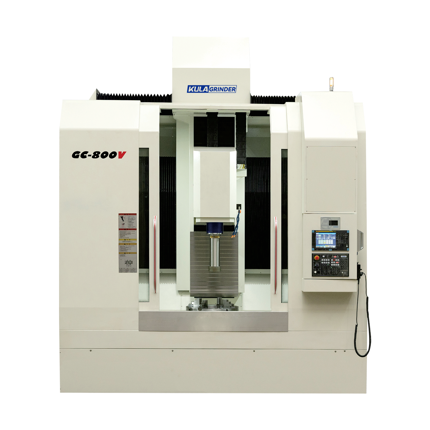
Evaluating a CNC Cylindrical Grinder for Internal Processing
Purchasing capital equipment requires mapping machine features directly to your production outcomes. Selecting the right grinder means looking far past the basic specification sheet.
- Quill Rigidity and Material: You must assess the material and the length-to-diameter (L/D) ratio of the grinding spindle. Heavy cutting forces push against the quill. If the L/D ratio is too high, the quill bends. Traditional steel quills work for shallow bores. For deep bores, you need solid carbide quills. Carbide offers significantly higher dynamic stiffness to minimize chatter and deflection.
- High-Frequency Spindles: Micro-bore applications demand extreme speeds. You must evaluate motorized spindles capable of 100,000+ RPMs. At these speeds, thermal expansion becomes a severe risk. Look for spindles featuring liquid cooling jackets to stabilize bearing temperatures.
- Coolant Delivery Systems: A grinding wheel spinning at 80,000 RPM creates a powerful air barrier. Standard flood coolant simply bounces off this invisible shield. You need high-pressure, through-spindle coolant or precision-engineered nozzles. These systems break the air barrier and flush chips forcefully from blind holes.
- Software & Control Capabilities: Hardware alone cannot solve every physical limitation. Look for CNC controls featuring built-in macro programming. Modern software manages automatic taper compensation, tracks wheel wear intelligently, and executes complex dressing cycles without operator intervention.
Implementation Realities: Cost, Tooling, and Setup Risks
Transitioning to an internal grinding process introduces unique daily challenges on the shop floor. You need clear strategies to manage tooling consumables, mitigate geometric errors, and streamline your machine setups.
Wheel Wear & Cycle Time Impact
Because internal wheels are exceptionally small, they contact the part more frequently per minute than large OD wheels. They wear down much faster. This rapid wear severely impacts your cycle times. Conventional aluminum oxide wheels require constant dressing to stay sharp. Every dressing cycle pauses production. Investing in superabrasives like CBN (Cubic Boron Nitride) or Diamond wheels changes the equation entirely. These advanced wheels hold their form significantly longer. They drastically reduce dressing frequency and keep your spindle in the cut.
The Taper Risk
Operators frequently battle a geometric defect known as "bell-mouthing." This taper effect happens near the entrance or exit of the bore. It occurs because the slender quill deflects under grinding pressure. As the wheel moves through the bore, pressure varies, causing the wheel to cut unevenly. A premium CNC Cylindrical Grinder mitigates this programmatic compensation. The control subtly adjusts the machine axes to counteract known deflection. Furthermore, programmers utilize "spark-out" cycles. Letting the wheel dwell without feeding relieves built-up pressure and straightens the bore perfectly.
Setup Complexity
Internal grinding setups demand serious operator skill. The grinding wheel centerline must align perfectly flush against the workpiece centerline. If the center-height alignment is off by even a fraction of a millimeter, part geometry suffers immediately. Manual alignment consumes hours of valuable production time. We highly recommend utilizing automated probing and in-process gauging systems. These sensors measure the bore dynamically during the cycle. They feed data directly back to the CNC control, eliminating human measuring errors and drastically reducing setup times.
Shortlisting Logic and Next-Step Actions
Do not simply request quotes based on a machine brochure. Your procurement strategy must rely entirely on verifiable data and your exact part geometries.
Defining Success Criteria
Buyers must map out their exact part families before speaking to machine tool builders. Document the maximum bore depth, minimum diameter, material hardness, and typical batch sizes. A machine built for shallow, high-volume bearing rings will fail miserably at grinding deep, low-volume aerospace landing gear cylinders. Knowing your extremes helps vendors size the spindle and coolant pumps correctly.
The Runoff Test
Never buy a grinder without a factory runoff. A factory runoff demonstrates machine capability on your actual parts under production conditions. Do not accept a runoff where the vendor simply produces one good part. Anybody can tweak a machine for a single golden sample. Demand sustained capability indexes. Look for a Cpk or Ppk greater than 1.33 across a batch of at least 30 parts. This proves the machine remains thermally stable and repeatable over time.
Evaluating Vendor Support
Grinding spindles eventually crash. High-frequency bearings wear out. Assess the manufacturer’s local service network carefully. Ask about their spindle rebuild turnaround times. Waiting six weeks for a spindle repair from overseas will devastate your production schedule. Furthermore, ensure they offer robust application engineering support to help your team optimize complex dressing cycles post-installation.
Conclusion
Mastering the internal grinding process remains a function of matching the right abrasives and parameters to a rigidly built, thermally stable machine. Deflection and heat are your two biggest enemies. By investing in stiff carbide quills, high-pressure coolant, and superabrasive wheels, you can overcome these inherent challenges easily. A well-configured machine transforms a bottleneck operation into a highly predictable, repeatable process.
Your next step should be conducting a thorough process audit of your current bore finishing methods. Identify exactly where your scrap occurs. Define your exact tolerance bottlenecks. Document your cycle times and wheel dressing frequencies. Armed with this data, you can engage machine tool builders confidently and specify a grinder designed to conquer your most difficult internal features.
FAQ
Q: What is the minimum bore diameter a CNC cylindrical grinder can process?
A: The minimum bore diameter depends heavily on spindle RPM limits and high-frequency spindle availability. With specialized motorized spindles spinning at over 150,000 RPM, modern grinders can successfully process bores down to just a few millimeters in diameter. However, specialized micro-abrasive pins and extreme coolant filtration are required at these micro scales.
Q: How do you prevent bell-mouthing in internal bore grinding?
A: You prevent bell-mouthing by minimizing quill overhang. Always use the shortest, stiffest quill possible. Utilizing carbide quills rather than steel drastically reduces deflection. Additionally, optimizing your spark-out passes and utilizing CNC taper compensation features will correct minor geometric deviations automatically during the final finishing cycle.
Q: Can a universal CNC cylindrical grinder perform both OD and ID grinding in one setup?
A: Yes. Universal grinders detail the use of B-axis indexing or drop-down swivel wheelheads. These mechanisms allow for consecutive external and internal grinding operations. Performing both operations without re-chucking the part ensures perfect concentricity between the outer diameter and the inner bore.
Q: Why is coolant delivery more difficult in internal grinding?
A: The high-speed centrifugal force of the grinding wheel creates an aerodynamic barrier that deflects standard flood coolant. Furthermore, the enclosed nature of a bore traps heat and chips. You must use targeted, high-velocity coolant nozzles or through-spindle delivery systems to puncture the air barrier and flush the zone safely.


