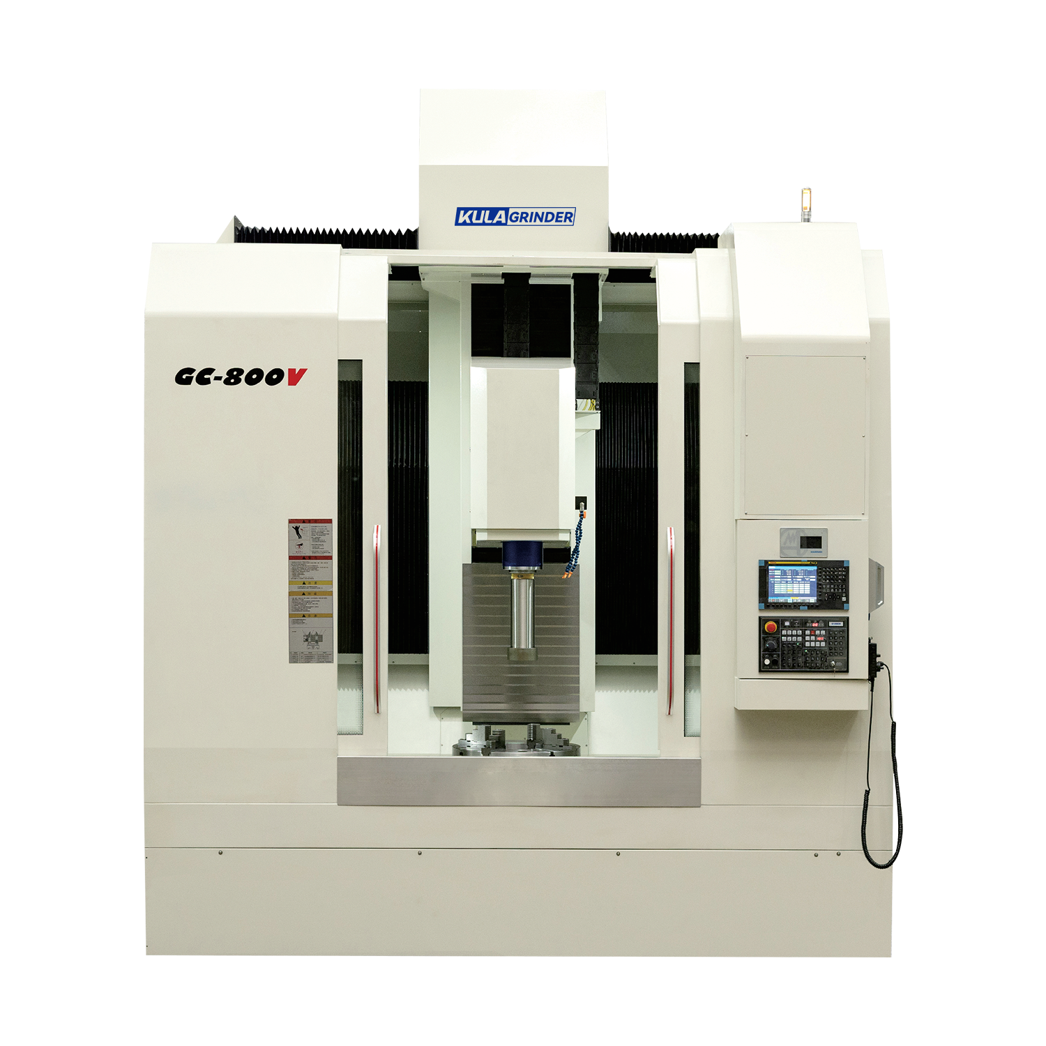
In high-precision manufacturing, the processing efficiency of a CNC Cylindrical Grinder dictates the baseline for cost-per-part and overall throughput. Machine shops constantly push for faster production times to stay competitive. However, operators frequently face a zero-sum trade-off on the factory floor. Increasing the Material Removal Rate (MRR) often compromises surface finish. This aggressive approach typically leads to scrap, rework, or excessive wheel wear.
You cannot simply turn up the feed rate and hope for the best. True efficiency requires a calculated, balanced approach. This article provides a systematic, evidence-based framework for optimizing grinding parameters, tooling, thermal management, and automation. We will explore how to safely maximize throughput without sacrificing part quality. By controlling variables and updating legacy practices, you will learn to unlock the full potential of your grinding operations.
Key Takeaways
Efficiency in cylindrical grinding relies on optimizing the G-ratio (material removed vs. wheel wear).
Upgrading to superabrasives (like CBN) and implementing strategic dressing cycles drastically reduces downtime.
Precise coolant velocity matching prevents thermal damage and allows for aggressive feed rates.
In-process gauging and automated workholding eliminate the non-cut time that drags down overall equipment effectiveness (OEE).
Diagnosing and eliminating surface defects (e.g., spiral lines, chatter) at the source prevents costly rework.
Establishing Process Baselines and Success Criteria
You cannot improve what you do not measure. Establishing clear baselines is the crucial first step before adjusting any machine parameters. Many operators tweak feed rates based on intuition, but sustainable efficiency requires hard data.
Define Efficiency Metrics
Success requires focusing on specific, measurable data points. Tracking these metrics reveals exactly where your process loses time and money:
Material Removal Rate (MRR): This measures the volume of material removed per minute. It serves as your primary indicator of cutting speed.
G-ratio: This calculates the volume of material removed divided by the volume of wheel wear. A higher G-ratio means your wheel lasts longer while doing more work.
Cycle Time Analysis: You must separate actual cutting time from non-cut time. Non-cut time includes loading parts, measuring, and wheel dressing.
Scrap Rates: Track the percentage of parts failing quality inspections due to poor surface finish or dimensional inaccuracy.
Identify Bottlenecks
Once you gather baseline data, you must differentiate between machining limitations and operational inefficiencies. Machining limitations involve physical hardware constraints. These include maximum spindle power or overall machine rigidity. If your CNC Cylindrical Grinder lacks the horsepower to push harder, you must upgrade the hardware.
However, operational inefficiencies cause most modern bottlenecks. Manual part loading, frequent wheel dressing intervals, and mid-cycle measurement pauses destroy throughput. Fixing these operational habits yields the highest return on your time investment.
The Trade-off Reality
Operators must acknowledge a harsh truth. Pushing machine limits without controlling variables leads directly to part deflection and severe thermal damage. Increasing wheel speed carelessly burns the workpiece. True efficiency scales only when you achieve process stability first. Solidify your foundational setup before chasing aggressive MRR targets.
Optimizing Grinding Parameters and Wheel Selection
A machine is only as effective as the abrasive it uses to cut metal. Rethinking your wheel selection and cutting parameters unlocks entirely new levels of production speed.
Abrasive Technology Alignment
Many legacy processes still rely on conventional aluminum oxide wheels. While affordable, they wear quickly when grinding hard aerospace alloys or tool steels. You should evaluate shifting to superabrasives like Cubic Boron Nitride (CBN) or Diamond.
Superabrasives hold their form significantly longer. They stay sharp, resist thermal breakdown, and dramatically reduce dressing frequency. Less time spent dressing means more time spent cutting parts.
Table: Conventional vs. Superabrasive Wheels
Feature
Aluminum Oxide (Conventional)
Cubic Boron Nitride (Superabrasive)
Workpiece Hardness
Low to medium (Standard steels)
High (Aerospace alloys, hardened steels)
Dressing Frequency
High (Requires frequent conditioning)
Low (Holds profile extensively)
Thermal Conductivity
Low (Retains heat at cutting zone)
High (Dissipates heat efficiently)
Initial Investment
Low
High
Speed Ratios
The relationship between grinding wheel surface speed (measured in RPM) and workpiece rotational speed defines cut quality. Finding the sweet spot prevents both wheel loading and excessive wheel breakdown. If your workpiece spins too fast relative to the wheel, the abrasive grains bite too deeply. This causes premature wheel wear. Conversely, spinning the workpiece too slowly creates rubbing instead of cutting, which generates massive amounts of heat.
Adaptive Feed Rates
Modern CNC software offers powerful tools we rarely utilize fully. Adaptive feed rate control allows the machine to vary feeds dynamically. You can program aggressive roughing passes tapering instantly to precise finishing passes based on real-time spindle load. As the wheel approaches the final dimension, the software automatically reduces the feed rate to achieve the exact required surface finish. This method eliminates arbitrary safety margins and reduces overall cycle time.
Strategic Wheel Dressing for Maximum Uptime
Dressing restores the cutting geometry of the wheel and exposes fresh, sharp abrasive grains. However, how and when you dress heavily dictates your overall machine uptime.
The Dressing Dilemma
Operators frequently fall into bad dressing habits. Over-dressing wastes valuable wheel life and eats into active production time. Some operators dress the wheel after every part just to feel safe. On the other hand, under-dressing leads to wheel loading. Metal chips fill the voids between abrasive grains, causing the wheel to burn the part and leave unacceptable surface defects.
Stationary vs. Rotary Dressing
Choosing the right dressing tool matters just as much as the frequency. Single-point or cluster diamond dressers work well for basic straight profiles. They remain simple and cost-effective. However, for complex profiles or superabrasive wheels, you should consider rotary diamond conditioning rollers.
Rotary dressers plunge into the grinding wheel, conditioning the entire profile simultaneously. This method reduces dressing cycle time from minutes to mere seconds. It ensures absolute profile consistency across thousands of parts.
Parameter Tuning
You must optimize the dressing overlap ratio and traverse feed rate. The speed at which the diamond traverses across the wheel directly impacts its cutting capability. A fast traverse creates an open, aggressive wheel face perfect for roughing. A slow traverse creates a closed, smooth wheel face for ultra-fine finishing. Mastering these parameters prevents the need for secondary polishing operations downstream.
Coolant Delivery and Thermal Management
Grinding generates immense friction. How you manage this thermal energy determines how fast you can run your CNC Cylindrical Grinder safely.
Thermal Constraints on MRR
Machine power rarely limits grinding efficiency. Heat serves as the primary limiting factor. When thermal energy builds up in the cut zone, it damages the metallurgical structure of the workpiece. This results in surface burns, micro-cracking, and part distortion. You must remove heat rapidly to maintain aggressive feed rates.
Velocity Matching
Simply flooding the machine with low-pressure coolant fails to cool the cutting zone. High-speed grinding wheels carry a dense layer of air around their perimeter. This air barrier literally deflects low-velocity coolant away from the cut.
Follow the engineering standard of coolant velocity matching. Your coolant delivery speed must match the surface speed of the grinding wheel. This precision breaks the air barrier and forces fluid directly into the grinding zone.
Nozzle Design and Filtration Best Practices
Upgrade to Programmable Nozzles: Standard copper tubes easily get bumped out of alignment. Programmable nozzles track the wheel diameter as it shrinks, ensuring perfect aim throughout the wheel's lifecycle.
Implement High-Efficiency Filtration: Recirculating dirty coolant acts like liquid sandpaper. It damages surface finish and loads the wheel.
Monitor Coolant Temperature: Use chillers to keep coolant at a constant ambient temperature. Fluctuating temperatures cause the machine frame and workpiece to expand and contract, ruining dimensional accuracy.
Elimating Scrap: Troubleshooting Common Defects
You cannot scale efficiency if you constantly produce scrap. Resolving surface defects remains an absolute prerequisite for speeding up production.
Diagnosing Spiral Lines (Feed Marks)
Spiral lines act as the most common pain point for grinding operators. These visible threads running along the workpiece usually point to a mechanical misalignment. Trace the causes systematically. First, check for an incorrect dressing lead; if the diamond traverses too quickly, it cuts a thread into the wheel. Next, inspect for uneven wheel wear. Finally, verify the alignment of your tailstock and headstock centers. A slight taper causes the wheel edge to dig into the part.
Eradicating Chatter
Chatter manifests as repeating visible ripples on the part surface. Spindle vibration, improper wheel balancing, or a lack of workpiece support forces operators to slow down feed rates defensively. When grinding long, slender parts, you must deploy steady rests to prevent part deflection.
Dynamic wheel balancing offers a permanent solution. An automatic balancer continuously adjusts counterweights inside the spindle hub while the machine runs. This eradicates microscopic vibrations, allowing you to increase RPM safely.
Increase coolant pressure; match wheel surface speed.
Inconsistent Sizing
Thermal expansion of part
Install coolant chiller; check for wheel loading.
Automation and In-Process Gauging Integration
Maximizing MRR only solves half the efficiency equation. To truly boost throughput, we must attack the idle time sitting between cutting cycles.
Reducing Non-Cut Time
Manual loading and unloading cripple a machine's daily output. Operators get tired, take breaks, and shift focus. Implementing robotic gantries or automated bar feeders eliminates these unpredictable pauses. A well-integrated robot loads a new blank and unloads a finished part in seconds, keeping the spindle turning continuously.
In-Process Measurement
Stopping the machine to check part diameters with manual micrometers introduces massive inefficiencies. It also introduces human error based on how hard the operator squeezes the gauge. Integrating CNC-linked touch probes or laser sizing gauges eliminates this downtime completely.
In-process gauging measures the part dynamically while the wheel grinds. Once the part reaches the exact target dimension, the gauge signals the CNC control to retract the wheel instantly. This guarantees perfect sizing every time and zero wasted seconds.
Scalability & Shortlisting Next Steps
Eventually, you must decide whether to retrofit existing equipment or invest in a modern, heavily automated machine. Retrofits work well for improving coolant delivery or adding basic probing. However, if your legacy machine lacks underlying structural rigidity, investing in new hardware makes financial sense.
When evaluating OEM vendors, use a brief checklist: Ensure they offer open-architecture software for easy automation integration. Verify their spindle designs provide maximum rigidity for superabrasives. Finally, demand robust local application engineering support to help you dial in complex part programs.
Conclusion
Processing efficiency is a holistic outcome. It results directly from the perfect alignment of machine rigidity, optimal abrasive selection, rigorous thermal control, and minimized idle time. You cannot simply adjust one dial and expect massive throughput gains. You must systematically balance MRR against dressing strategies and coolant delivery.
We advise production managers to start by conducting a strict time-study on their current cycle times. Specifically, isolate your non-cut time before investing in expensive new hardware. Often, fixing loading routines and dressing habits yields immediate double-digit efficiency gains.
Take action today. We encourage you to consult an application engineer or request a tailored time-study for your specific high-volume parts. A professional test grind will quickly reveal exactly where your process leaves money on the table.
FAQ
Q: What is a good G-ratio in CNC cylindrical grinding?
A: Acceptable G-ratios vary wildly depending on the abrasive and workpiece. For conventional aluminum oxide wheels cutting standard steel, a G-ratio of 30:1 to 50:1 is typical. However, when using superabrasives like CBN, a good G-ratio easily exceeds 10,000:1. You track it by measuring the exact volume of material removed divided by the volume of wheel lost after a set production run.
Q: How can I stop spiral lines from appearing on the workpiece?
A: Spiral lines usually stem from poor dressing mechanics or alignment issues. To stop them, first reduce your dressing traverse feed rate. Ensure your dressing overlap ratio is tight enough to create a smooth wheel face. Check the diamond tool for excessive wear. Finally, verify wheel balance and ensure your tailstock and headstock centers are perfectly aligned without taper.
Q: Does increasing wheel speed always improve efficiency?
A: No. Increasing wheel speed beyond the optimal zone creates severe risks. Exceeding safety limits can cause catastrophic wheel failure. Additionally, spinning the wheel too fast without matching the workpiece speed and coolant velocity drastically increases friction. This quickly leads to severe thermal damage and wheel loading, which ultimately destroys process efficiency.
Q: What is the ROI on in-process gauging for cylindrical grinders?
A: The ROI is exceptionally high, often paying for itself within months. In-process gauging eliminates manual measurement downtime and virtually eradicates scrap caused by under or over-grinding. For tight-tolerance aerospace or automotive parts, it ensures 100% dimensional compliance while allowing the machine to run unattended, dramatically lowering labor costs per part.